IEC 61850 deals a lot with IEDs. But: What is an IED?
First you can check with two documents of the series IEC 61850:
IEC 61850-1 - Intelligent Electronic Device (IED)
any device incorporating one or more processors with the capability of receiving or sending data/control from or to an external source (for example, electronic multifunktional meters, digital relays, controllers)
IEC 61850-1 - Physical Device (PD)
equivalent to an IED as used in the context of this standard
IEC 61850-5 - Intelligent electronic device (IED)
device incorporating one or more processors with the capability to execute application
functions, store data locally in a memory and exchange data with other IEDs (sources or sinks) over a digital link
Many years after these definitions have been published, we have different views on the term IED:
Physical IED (in the context of IEC 61850 and IEC 61400-25) - any physical device incorporating one or more processors with the capability of exchanging information (derived from IEC 61850 information models and exchanged with IEC 61850 services for client/server and publisher/subscriber) with other physical device(s). The semantic, the coding and decoding of the exchanged information (messages) follows the standard series.
IED Configuration (in the context of IEC 61850 and IEC 61400-25) - formal description (section in the SCL according to part 6) of the IEC 61850 information models linked to the IEC 61850 information exchange roles client, server, publisher, or subscriber, and the signal flow between physical IEDs.
IED Role (in the context of IEC 61850 and IEC 61400-25) - implementation of the IED Configuration: implementation of the IEC 61850 information model plus implementation of any combination of the following information exchange roles: client, server, publisher, or subscriber.
A Physical IED can host any combination of IED Roles.
Note: A gateway may host a server role to an up-link (first SCL file plus a client role and a subscriber role (both configured in a second SCL file) to the underlying Physical IEDs.
Please note that in SCL a Server configuration comprises the models including the DataSets, Report Control Blocks, GOOSE Control Blocks, SV Control Blocks, and Log Control Blocks:
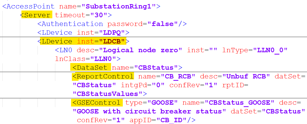
From a communication point of view GOOSE and SV publisher and subscriber are NOT part of the client/server communication ...
I hope this definition will help to reduce the disconnects in the communication of the experts.
Let me know what you think.

.jpg)


